EcoMBR1 - Build it yourself
Pin assignment and 3D-printed enclosure
Pin assignment
For building your own: the firmware runs on an ESP32 relay board with built-in power supply and uses these pins:
| Function | Pin |
|---|---|
| Relay | IO16 |
| Status LED | IO23 |
| ModBus transmit / receive | GPIO1 (TX) / GPIO3 (RX) on the pin header (3) |
| "Permanently on" switch | IO19 to GND (internal pull-up) |
| Buttons | EN (restart), IO0 |
The RS485 converter (TTL to RS485) is connected to 5V, GND, TX and RX of the pin header. It must switch the transmit direction by itself, because the firmware does not drive a separate pin for that.
Enclosure
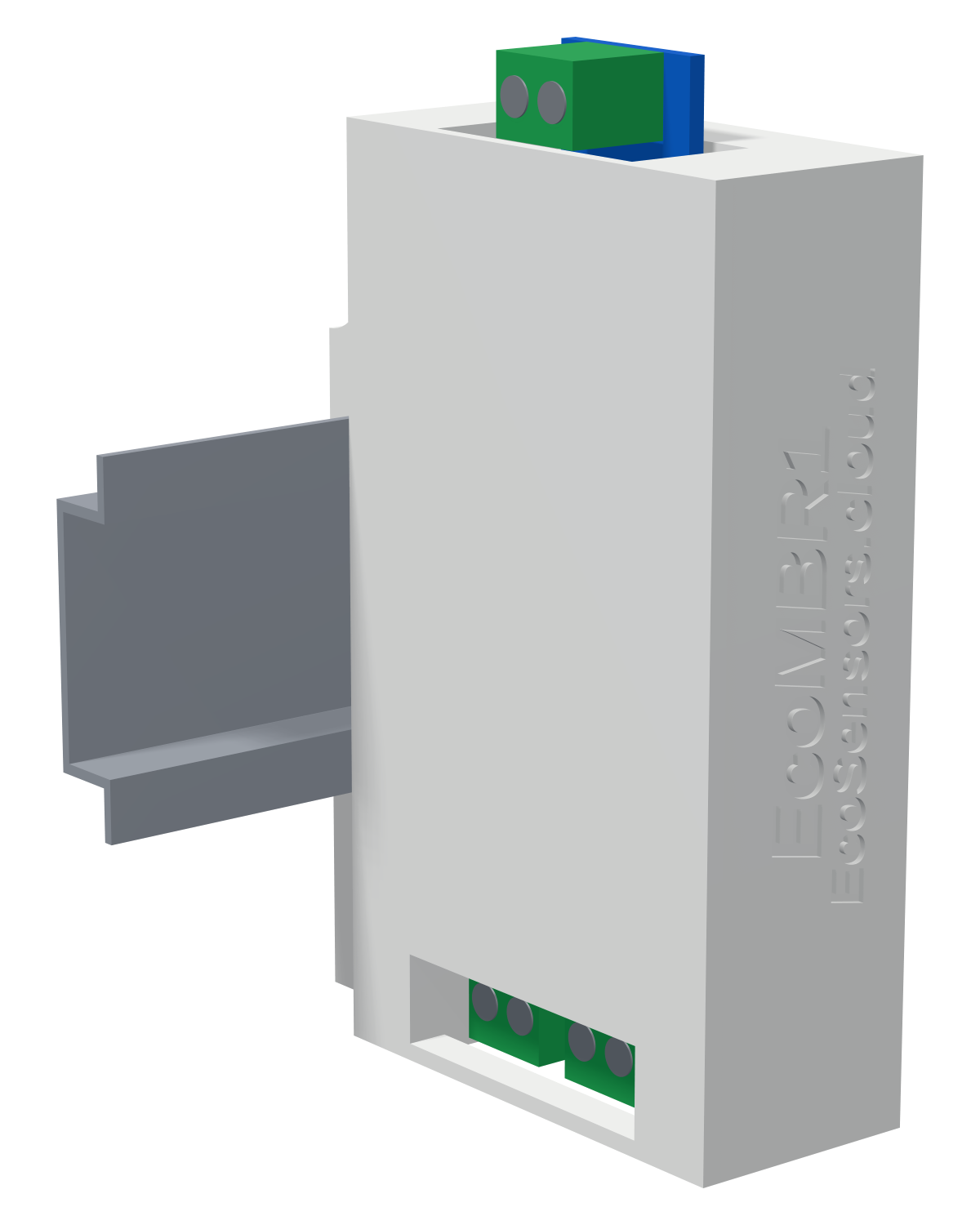
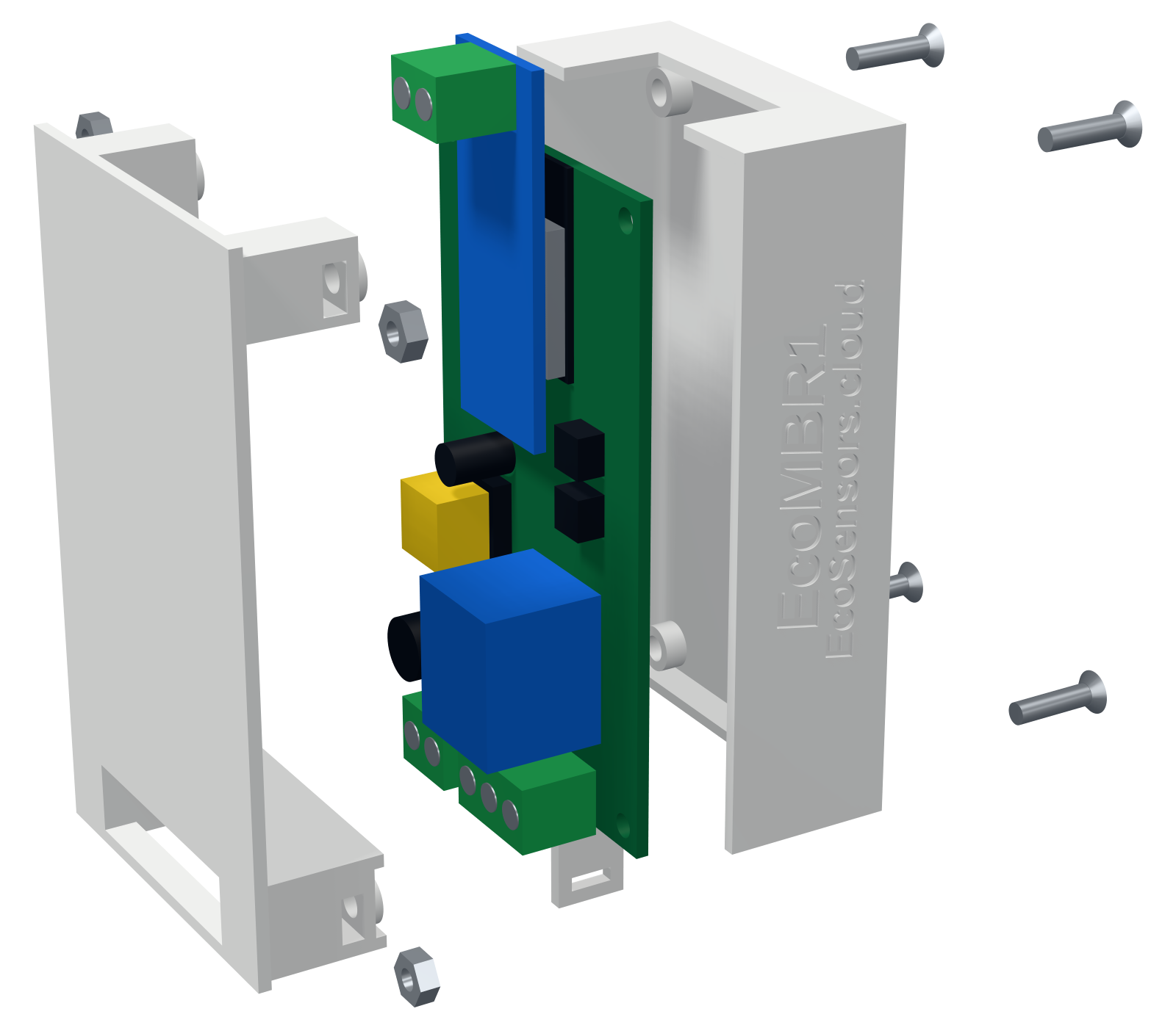
You can make the enclosure of the EcoMBR1 yourself on a 3D printer. It sits on a DIN rail (TS 35), measures 86 × 23 × 54 mm (H × W × D) and consists of three parts. The board lies against the side wall of the base, and the cover holds it with four screws. The mains and relay terminals sit in an open compartment at one end of the enclosure. At the other end the A/B terminal of the RS485 converter sticks out. Both stay accessible with the cover closed.
Print files
| Part | File | |
|---|---|---|
 |
Base with rail mount and four standoffs for the board | ecombr1‑base.stl |
 |
Cover with screw blocks and a partition behind the terminals | ecombr1‑cover.stl |
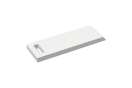 |
Slider that locks the enclosure on the DIN rail | ecombr1‑clip.stl |
- The parts are already oriented for printing in the files. No support material is needed.
- Print the enclosure in ABS or ASA if you can. If neither is available, PETG works as well. PLA is not heat-resistant and therefore unsuitable.
- Print with a 0.4 mm nozzle and 0.2 mm layer height.
Assembly
You also need 4 countersunk screws M3 × 12 and 4 hex nuts M3.
- Slide the nuts sideways into the slots of the four cover blocks.
- Place the board with its component side on the blocks of the cover. The RS485 converter lies above the ESP32 module, and its screw terminal sticks out through the cut-out in the end wall. The enclosure is designed for a converter with a board of about 17 × 45 mm.
- Put the base on top and screw it down from the outside with the four screws.
- Push the slider into the guide on the back. Hook the enclosure onto the DIN rail with the fixed hook, press it on and push the slider under the rail.
The enclosure is meant for installation in a closed distribution board. It does not protect against dust or moisture.